A gyroscope is used in aviation and the aerospace industry to stabilise the position or as a navigation tool in so-called inertial navigation. The basic element of a gyroscope is a rapidly rotating mass. A free gyro tends to maintain the position of its rotational axis in space independently of gravity. This property is exploited in the artificial horizon in the aircraft. If the gyro wheel is mounted in a gimbal, it is referred to as a guided gyroscope. If a force acts on a guided gyroscope perpendicular to the axis of rotation, the gyroscope exerts a moment: the gyroscopic moment. The rotation perpendicular to the axis of rotation is known as precession. A gyroscope therefore has three axes: the axis of rotation (spin axis), the precession axis (output axis) and the axis of the gyroscopic effect that triggers the gyroscopic moment (input axis). All are perpendicular to each other.
The TM 630 unit demonstrates the properties of guided gyroscopes. The moments caused by the precession can be experimentally determined.
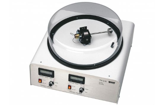
The gyroscope is composed of a flywheel mass that is driven at high speed by an electric motor. The gyro wheel is mounted in a cardan frame. The frame can be rotated about the vertical axis by a second electric motor. This generates the precession of the gyroscope. By means of the precession, the gyroscope exerts a moment – the gyroscopic moment – about the horizontal axis. The gyroscopic moment causes deflection of the inner frame. The gyroscopic moment can be determined with a lever and a sliding weight.
The speeds of both electric motors for rotation and precession can be adjusted and are displayed digitally.
A transparent protective cover above the rotating arm ensures safety: operation is only possible when the protective cover is properly attached.