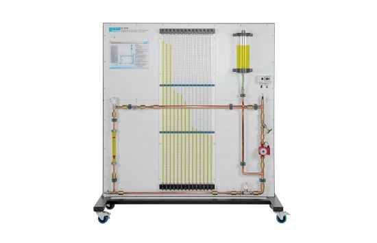
When water flows through a pipe system there are resistances as a result of changes in direction, valves and fittings and pipe friction. The flow resistances are directly dependent on the geometry of the pipe elements and the number and type of fittings. In addition, the flow velocity plays a key role in the occurrence of pressure losses.
The HL 210 unit can be used to investigate and visualise the pressure distribution in a pipe system. The trainer enables the examination by experiment of different influencing factors on the pressure losses in real pipe systems. The relationship between pump characteristic and system characteristic is studied in the experiment. The pipe elements used are commercially standard components in heating and sanitary engineering. The clear panel is mounted on a sturdy, movable frame.
The trainer can be operated independently from the mains water network and is equipped with a pump and a water tank. Pipe elements with varying radii and straight pipes with varying diameters are located in a closed water circuit. In addition, various standard valves from heating engineering are also installed. There are pressure measuring points between the various elements in order to determine the pressure loss of each pipe element.
The respective pressures can be read via the tube manometer with reference to the height of the liquid column. The flow rate is measured by and read from a rotameter.

